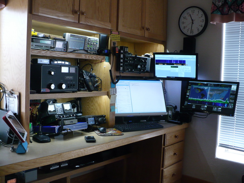
Here is our shack and antennas. Updated November 2019
Link to the new Windom Fan Dipole installed in 2012!
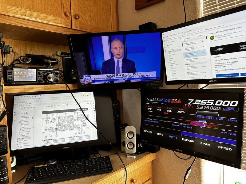
March 2024 Flex gone Yaesu Ft-DX10 in the Shack
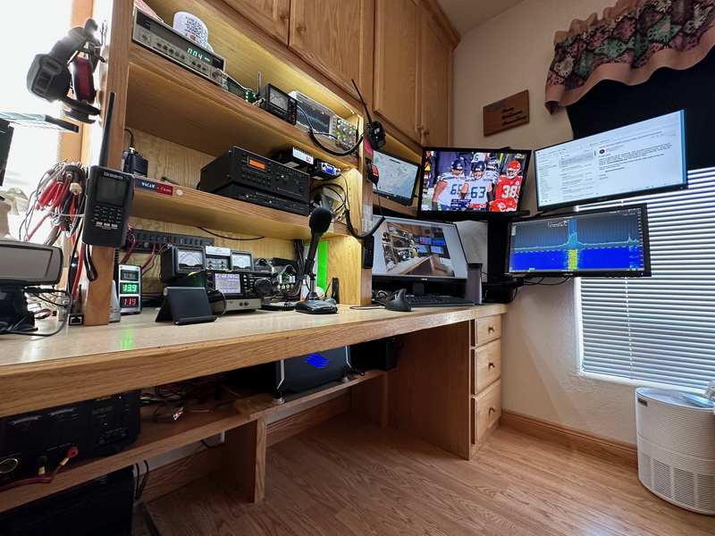
November 2019. New Elecraft KPA500/KAT500.
Now I can run power remote!
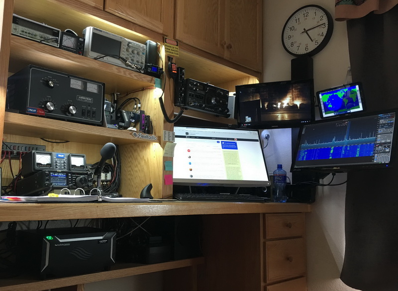
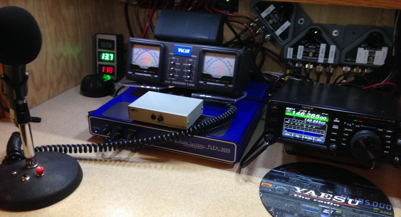
January 2018 Update. Finally got a Flex 6400
March 2024 Sold the Flex, bought a Yaesu FT-DX10
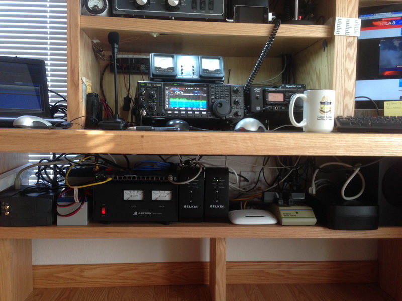
Tucked away on the bottom shelf. It's a network "appliance". Also new a Samsung tablet above the Flex monitor.
January 2018 Update
Replaced laptop on the right with a 21" monitor. Now dual monitors
on the main Win 10 PC. Added Azulle Win 10 memory stick PC
to TV set. Showing SDR on screen. Tried
several other PC sticks with poor results.
|
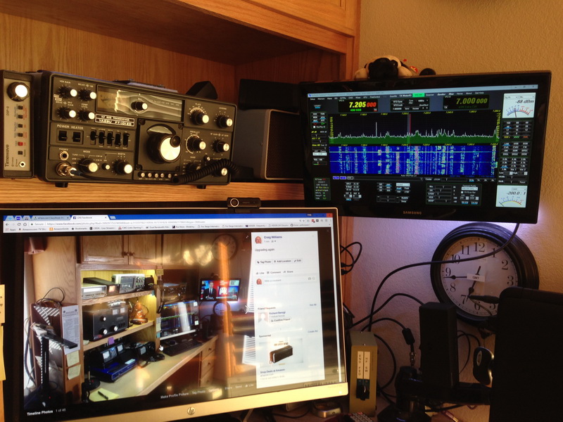
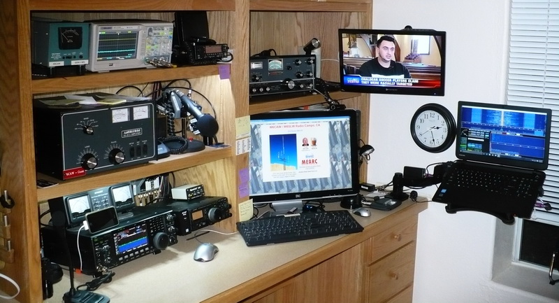
February 2017 Update Upgrading! Replaced the 7600 with a FlexRadio 3000. Great fun. Replaced FT-897D with a Yaesu FT-991A. Our Club repeater will be the Yaesu analog/digital Fusion. To the right of the scope a QYT KT-7900D quad band direct from Communist China. My Yaesu FT-101ZD MarkII in the vintage position.
We can put the FLEX on the 19" TV. Multiple monitors are easy with Windows 10 and a video card with multiple video outputs.
A/B microphone switch. not wanting to pay $120.00 and up for a simple A/B switch I hit the internet. Both my FLEX and 991A use the same pinouts so, I found a Ethernet A/B switch on Ebay for $6.98 Found 2 foot, shielded CAT-5 cables for $1.66ea from SF Cable. Works great, no hum.
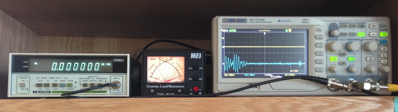
I love test equipment! Counter connected to an Efratom MFS-300U-01 GPS enabled frequency standard.
October 2015 update Also a Toshiba laptop connected to an SDRplay receiver. ( Now sold at your local HRO ) The laptop is on a 2 in 1 FLEXIMOUNTS L01 Full Motion LCD Arm,Laptop Desk Mount form amazon. Best mount I have ever had or seen!
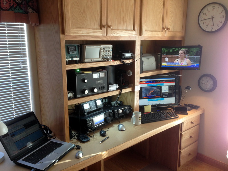
June 2015. The XYL got new flooring and carpets and we got a new wall to wall office and shack. Above the new, main, operating position.
A shelf under to put the heavy supply, UPS's and router on. New AC outlets, 40A of 120V, 20A of 240V.
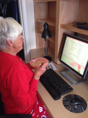
The left side. Sandi's, W6SLW workstation. March 2015 update. Found a killer deal on a 4 week old Icom IC-7600. The PRO-III will be moved to the Jacumba Hot Springs Community Center as part of their new "disaster" Shack. New 2014.
Replaced the Motorola Test Set with an IFR 1500. Ameritron AL-811 with RF Parts 811H Russian tubes installed, and
a Heathkit HM-2103 R.F. Load / Wattmeter. With my new Windom Fan Dipole I can load the amp from 160 to 10 Meters without an antenna
tuner! I am driving it with a 756 PRO III. The base mike on the PRO III ( now 7600 ) is a Icom IC-SM-30 with a
Turner Sidekick 100 as backup. Update November 2014 more stuff. Added a Siglent SDS 1072CML storage scope. Things have sure changed since the 60's. The Siglent is a 70 Mhz, 2 channel, storage scope for $319.99! The monitor over the big monitor is actually a Element 19" TV with every input you can imagine. Here it is hooked up to a Gateway Netbook. The big monitor is hooked to my Windows 7 PC and a FUNcube Dongle running SDR Console V2.3 Beta. I input the low level audio out of the back of the PRO-III, now 7600, and send it to the scope and the iphone. On the I phone I run the Black Cat Systems Spectrum application to monitor received audio. Channel 2 of the scope is connected to the RF monitor ports of the Comet 2300. Much fun!
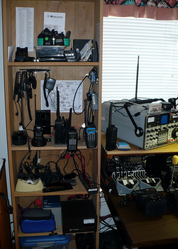
June 2015. All of this is moving around with the new cabinets. My book case radio rack top to bottom. Full of scanners and spare
Ham HT's and batteries. Antenna switches to control antennas on the end of the house tower below.
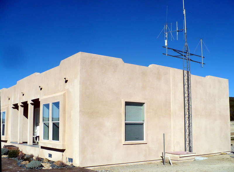
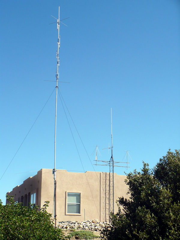
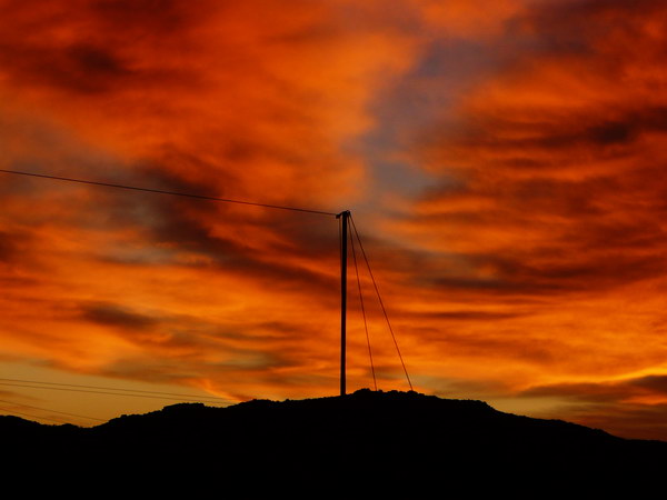
January 2012 a new tower for 50 MHz and up. We had to stucco the house and fix the roof so no holes in the house allowed. Our elevation is 3025 feet above sea level.
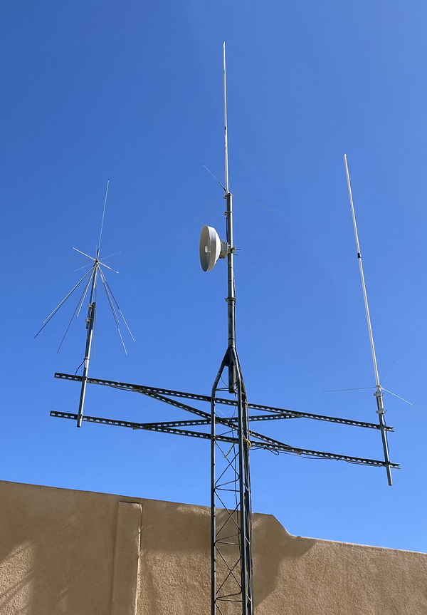
2022 Tower close up.. Diamond
Discone. 5GHz NanoStation wireless Internet transceiver/dish below.
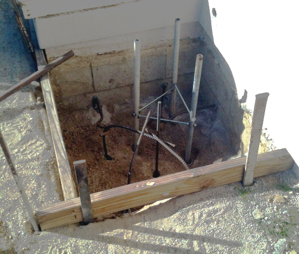
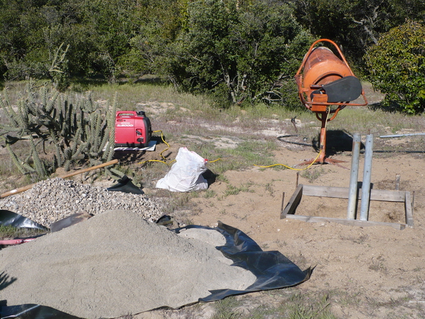
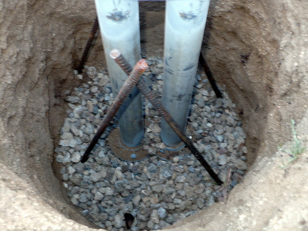
The hole for the tower. The 2 sides next to the house have 4 rods glued into holes in the house foundation as the bottom of the hole is the top of a granite boulder! My friend KJ6NTB drilled holes into the bolder to set in the rebar and water pipe home made tower mount.
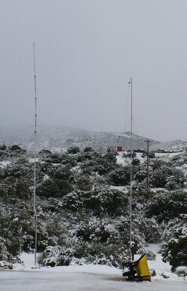
September 2012. Replaced the Cushcraft R7000 with an R7 40M through 10M vertical. The 7000 developed trap problems on several bands.Mounted about 50 feet South of the house. With 60 MPH + wind gusts during the Santa Anna winds we need lots of guy wires up here.
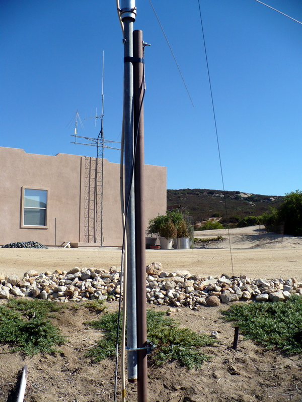
This time I built a tilt over mount for the R7. A 1" ID well pipe is forced into a PVC pipe cemented into the ground. The tilt over is a left over piece of 1" pipe. Just drilled a hole in both and added a bolt for a pivot. The bottom is held with a left around antenna U clamp. Again, never throw anything away. March 2012 the new Windom Fan Dipole!I loved my old 160 Meter Windom ( or off center fed dipole for the purest ) but it did not work very well on 80 Meters. I use 80 and 40 Meters a lot so after a year of pondering I present the new, improved, 160/80, Windom Fan Dipole!
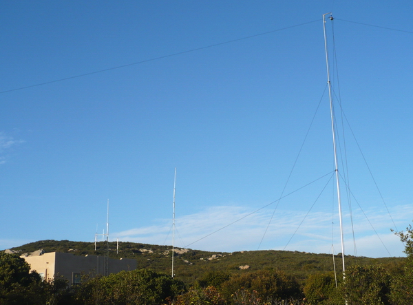
This new Windom has the 160 Meter leg pointing 306 degrees NW and the 80 Meter leg pointing 47 degrees NE. It was not placed with any great knowledge of the antenna patterns but placed where it was easy for the terrain.
The Hole
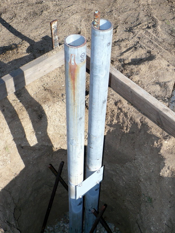
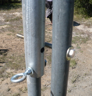
The tilt up vertical supports are 2 1/4 inch thick wall pipe.
The bolted on brace keeps the spacing for the future mast.
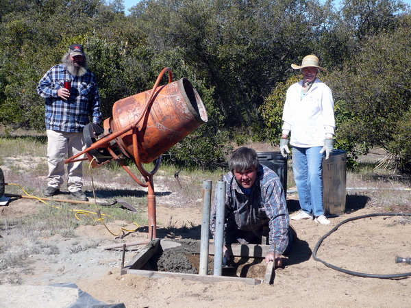
Ken's neighbor. Ken KI6HPM. Wife Sandi W6CAW.
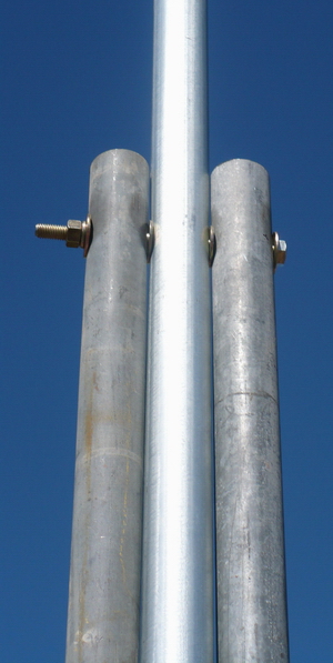
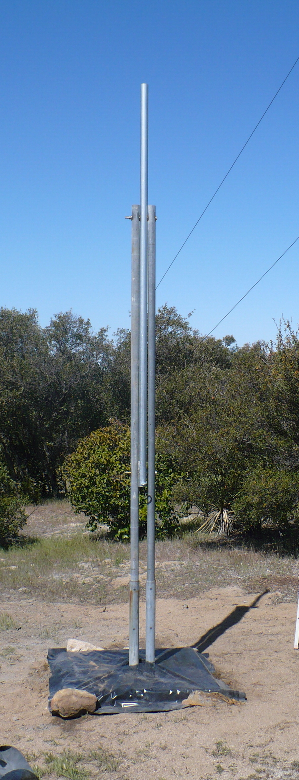
The first mast section installed in the tilt up
The finished tilt up waiting for the rest of the mast. I use conduit from my local hardware store.
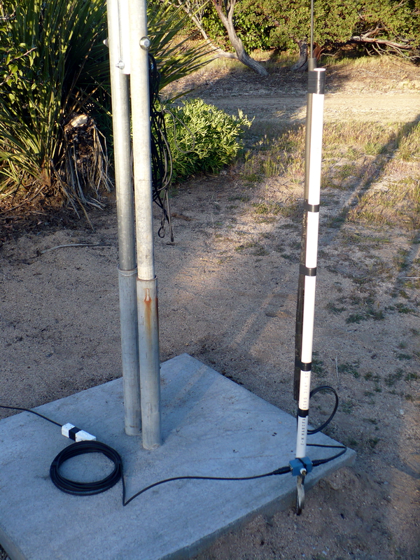
Finished base. As in the old Windom I use snap on torroids for the current balun. The PVC slipped over the ground rod gives me something to tape the down lead to. The next project is running LMR400 from the shack to the antenna.
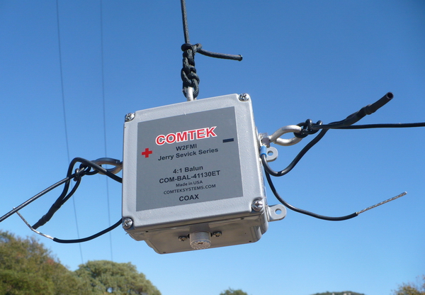
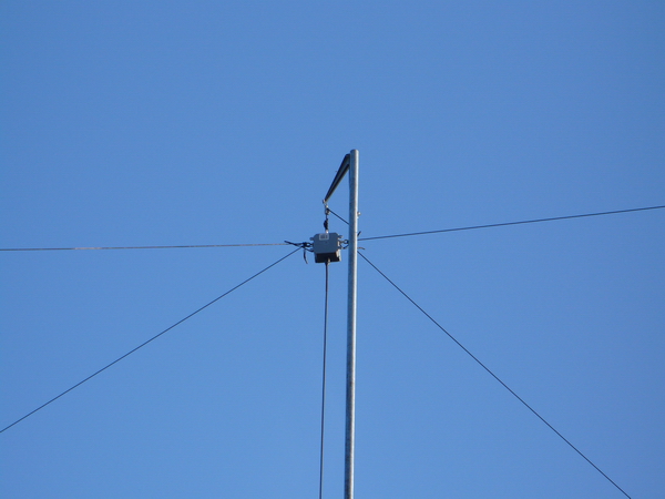
New 4/1 balun from DX Engineering. Only 160M wires attached so far.
New balun in the air with both Windom's attached. The top is at 44 feet. I used pulleys this time so I could play with the wires without tilting down the mast.
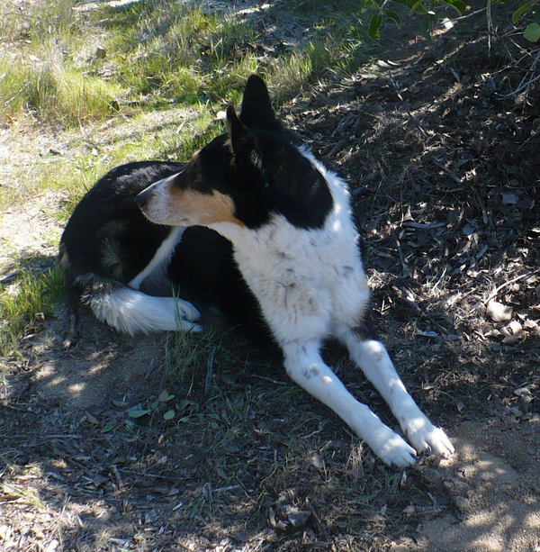
Xena Warrior Princess (RIP May 2013.) gives it a final look over.
Update December 2013December 2013 update. I just replaced the RG8x feed line to the antenna with Times Microwave LMR400. ( Their site also has an excellent cable loss / characteristic calculator.) I did this as measurements seem to show the reactance of the 8x was effecting the SWR in the shack. Using the RigExpert AA-54 analyzer the graph below shows a 0 to 54Mhz sweep of the Windom. Click the graph for a larger image. The light graph is the sweep at the base of the antenna, 50' of 8x down lead. The dark is a scan in the shack, end of the 98' LMR400 run. Vertical axis = VSWR, horizontal = frequency. To download the data files right click on the following links and save them to your drive. Full Range at antenna base. Full range at shack. RigExpert allows you to download the AntiScope software from their website and run my data file so you can see the massive amount of information available in the file as you move your cursor over the graph. Obviously an evil marketing plan to get you to buy their products.
The graph below shows more detail on the 0 to 20 Meter range.
Very strange stuff below 80 Meters? Why there is such a difference in every measurement parameter below the 80 Meter band is a mystery to me. I assume it has something to do with the reactance of the cable? Hopefully someone with an answer will email it to me and I can post it here. Meanwhile, the antenna will still tune on the Ameritron AL-811 amp without an external tuner and my PRO III does not do a fold back on the power. Always more to learn!
Additional RigExpert graphs at this link.
Follow this link to my first Windom in 2008.
So that's the latest from Campo. Hope you enjoyed checking out my projects Craig Williams W6CAW
2 good links to Windom antennas Link to a Excel spread sheet to calculate dipole antennas. Study on feed point impedance for OCF antennas. W6CAW Antenna Test Range Projects
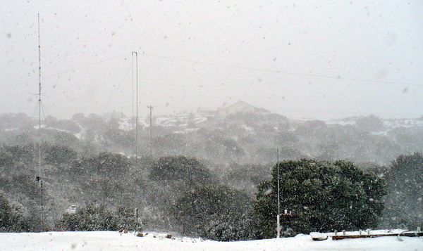
March 2012 more snow on my new Windom before the 80 Meter wire went up.
|